


Cassini
Principal Investigator: Dr. Ralf Srama
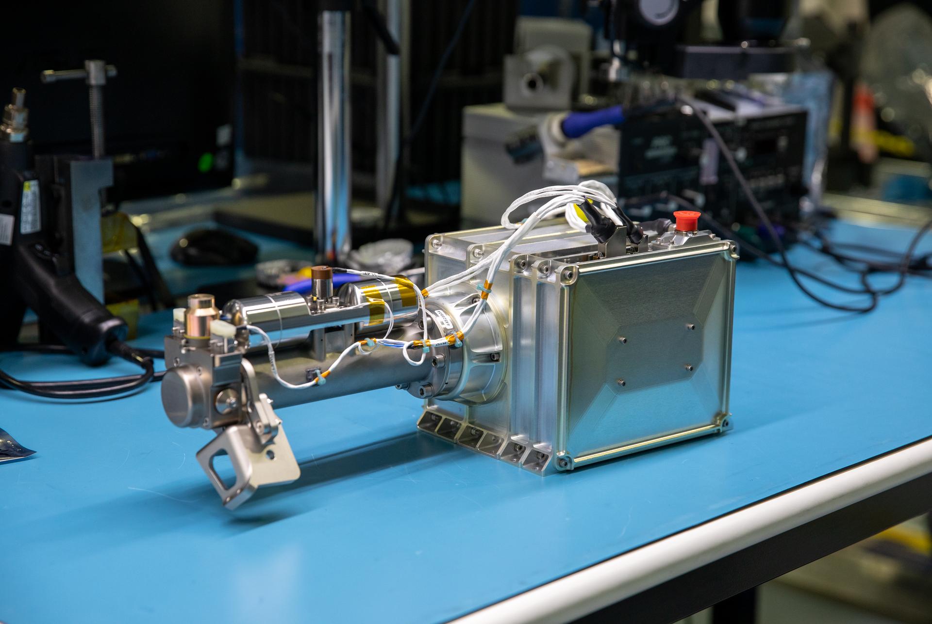
CDA General Description:
The Cosmic Dust Analyzer (CDA) is intended to provide direct observations of particulate matter in the Saturnian system, to investigate the physical, chemical, and dynamical properties of these particles, and to study their interactions with the rings, icy satellites, and magnetosphere of Saturn.
CDA Scientific Objectives:
- To extend studies of interplanetary dust (sizes and orbits) to the orbit of Saturn.
- To define dust and meteoroid distribution (sizes, orbits, composition) near the rings.
- To map the size distribution of ring material in and near the known rings.
- To analyse the chemical compositions of ring particles.
- To study processes (erosional and electromagnetic) responsible for E ring structure.
- To search for ring particles beyond the known E ring.
- To study the effect of Titan on the Saturn dust complex.
- To study the chemical composition of icy satellites from studies of ejecta particles.
- To determine the role of icy satellites as a source for ring particles.
- To determine the role that dust plays as a magnetospheric charged particle source/sink.
CDA Sensing Instruments:
- Dust Analyzer.
- High Rate Detector.
CDA Instrument Characteristics:
- Mass (current best estimate) = 16.36 kg
- Peak Operating Power (current best estimate) = 18.38 W (including articulation)
- Average Operating Power (current best estimate) = 11.38 W
- Peak Data Rate (current best estimate) = 0.524 kilobits/s
- Dimensions (approximate) = 50.7 cm length x 45.0 cm diameter; 81 cm x 67 cm x 45 cm overall
Engineering Writeup
The Cosmic Dust Analyzer Subsystem (CDA) will provide direct observations of dust and ice particles in interplanetary space and in the Jupiter and Saturn systems. It will investigate the physical, chemical, and dynamical properties of these particles matter as functions of the distances to the Sun, to Jupiter, to Saturn, and to Saturn's satellites and rings. Finally, it will study the interaction of the particles with the Saturnian rings, satellites, and magnetosphere.
The four major functional elements of the CDA are:
Dust analyzer
Main electronics
Articulation mechanism
High-rate detector assembly
CDA Links
The dust analyzer (DA) consists of the following components:
Four charge pick-up grids
Hemispherical target
Ion collector
Electron multiplier
Sensor electronics
DA Links
The charge pick-up grids collect the initial impact particles. They are mounted at the entrance of the sensor.
The hemispherical target is divided into two parts -- a ring-shaped impact ionization target and a chemical analyzer target in the middle of the ionization target. The chemical analyzer target has an acceleration grid mounted 3 mm in front of it.
The ion collector has a grid that is negatively biased in order to collect the positively charged plasma ions produced at the impact ionization target.
The electron multiplier is located in the center of the hemispherical ion collector target. It amplifies the signal produced by ions capable of penetrating the ion collector grid. These ions originate from plasma produced by particle impact either on the impact ionization target or the chemical analyzer target. The output signal from the multiplier differs depending upon the target from which impacts are being measured.
The sensor electronics are contained in an electronics box attached to the DA sensor chassis. Among other components, this box contains charge-sensitive amplifiers (CSAs) that measure the signals from all of the grids in the DA.
The CDA main electronics includes amplifiers and transient recorders, a control and timing unit, a microprocessor unit, a bus interface unit, a power input circuit, a low-voltage converter, and a housekeeping system.
All CSA and electron multiplier signals are separately amplified by logarithmic amplifiers and then digitized by an analog-to-digital converter. The data are stored on transient recorders. Only the recorder connected to the pick-up grids is operated continuously. All others are activated only by a signal detected at a target or the acceleration grid. The control and timing unit stores and decodes information received from the microprocessor and produces all timing and synchronization signals required for instrument operation.
The microprocessor samples and collects the buffered measurement data, coordinates the subsystem measurement cycle, controls the instrument operating modes, processes the data according to a program loaded in its memory, and outputs data to the spacecraft upon request through the bus interface unit (BIU). The BIU is the interface circuit between the spacecraft and the microprocessor and is powered by the CDA instrument. The power input circuit is the interface with the spacecraft Power and Pyrotechnics Subsystem (PPS) and contains a filter circuit and a regulator to produce a d.c. voltage to feed the low-voltage converter.
The low-voltage converter is a d.c./d.c. converter that provides different regulated low voltages for the electronics circuits and the supply voltage for the high-voltage converters. The converters are synchronized to the 100-kHz clock provided through the BIU from the Command and Data Subsystem (CDS).
The CDA housekeeping system is a data system that multiplexes, digitizes, and stores information on the instrument current, the low voltages, the high voltages, and temperature measurements.
The articulation mechanism (AM) allows the entire CDA instrument, including the high-rate detectors, the dust analyzer, the main electronics, and the articulation mechanism electronics, to be rotated or repositioned with respect to the spacecraft coordinate system.
The high-rate detectors (HRDs) are two redundant independent sensors. The electronics for the sensors are contained in the HRD electronics box, and each sensor has its own electronics, independent of the other sensor. The HRD will be operated in two modes: "normal" mode and "calibrate." In the normal mode, the operational HRD continuously collects dust particle data. In the calibrate mode, a calibration cycle is initiated, which consists of a sequence of pulses sent to the HRD by the in-flight calibrator (IFC) to verify the stability of the electronics.
Cassini Orbiter Instruments
They surveyed and sniffed, analyzed and scrutinized. They took stunning images in various visible spectra. Cassini's 12 science instruments were designed to carry out sophisticated scientific studies of Saturn, from collecting data in multiple regions of the electromagnetic spectrum, to studying dust particles, to characterizing Saturn's plasma environment and magnetosphere.
Optical Remote Sensing
Mounted on the remote sensing pallet, these instruments studied Saturn and its rings and moons in the electromagnetic spectrum.
- Composite Infrared Spectrometer (CIRS)
- Imaging Science Subsystem (ISS)
- Ultraviolet Imaging Spectrograph (UVIS)
- Visible and Infrared Mapping Spectrometer (VIMS)
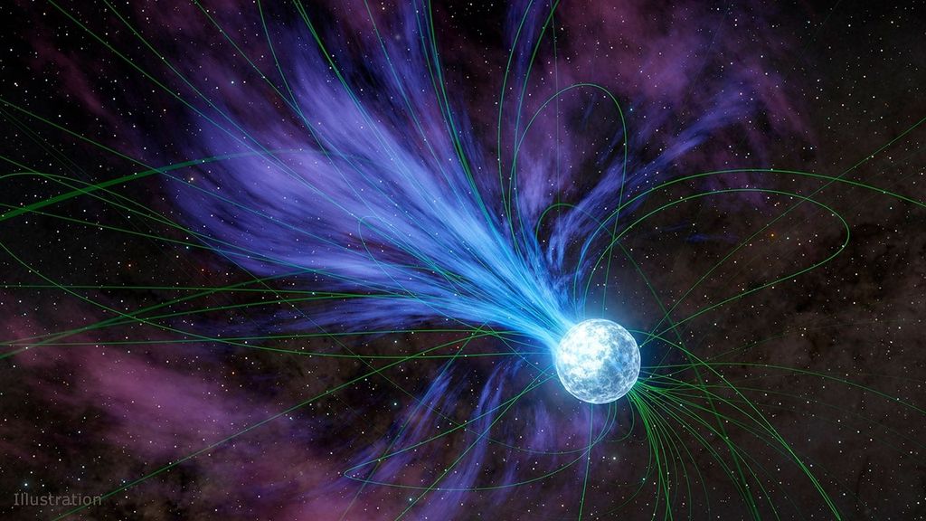
Fields, Particles and Waves
These instruments studied the dust, plasma and magnetic fields around Saturn. While most didn't produce actual "pictures," the information they collected is critical to scientists' understanding of this rich environment.
- Cassini Plasma Spectrometer (CAPS)
- Cosmic Dust Analyzer (CDA)
- Ion and Neutral Mass Spectrometer (INMS)
- Magnetometer (MAG)
- Magnetospheric Imaging Instrument (MIMI)
- Radio and Plasma Wave Science (RPWS)
Microwave Remote Sensing
Using radio waves, these instruments mapped atmospheres, determined the mass of moons, collected data on ring particle size, and unveiled the surface of Titan.