


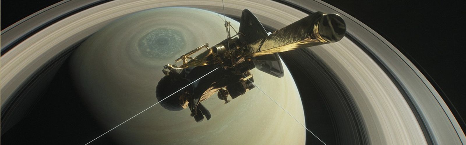
Cassini
Principal Investigator: Virgil G. Kunde
The Composite Infrared Spectrometer (CIRS) consists of dual interferometers that measure infrared emission from atmospheres, rings, and surfaces over wavelengths from 7 to 1000 micrometers (1400 to 10 cm-1) to determine their composition and temperatures.
CIRS Scientific Objectives:
- To map the global temperature structure within Titan's and Saturn's atmospheres.
- To map the global gas composition within Titan's and Saturn's atmospheres.
- To map global information on hazes and clouds within Titan's and Saturn's atmospheres.
- To collect information on energetic processes within Titan's and Saturn's atmospheres.
- To search for new molecular species within Titan's and Saturn's atmospheres.
- To map the global surface temperatures at Titan's surface.
- To map the composition and thermal characteristics of Saturn's rings and icy satellites.
CIRS Sensing Instruments:
- Far-Infrared Focal Plane [FP1] (16.67 to 1000 µm; 4.3 mrad circular field of view)
- Mid-Infrared Focal Plane [FP3] (9.09 to 16.67 µm; 1x10 array of 0.273 mrad squares)
- Mid-Infrared Focal Plane [FP4] (7.16 to 9.09 µm; 1x10 array of 0.273 mrad squares)
CIRS Instrument Characteristics:
- Mass = 39.24 kg
- Peak Operating Power = 32.89 W
- Average Operating Power = 26.37 W
- Peak Data Rate = 6.000 kilobits/sec
- Dimensions = 50-cm diameter telescope; 89 cm x 76 cm x 52 cm
The Composite Infrared Spectrometer (CIRS) is designed to measure infrared energy of various wavelengths in the Saturnian system. It addresses a wide variety of science objectives for the atmospheres of Saturn and Titan, and for Saturn's icy satellites and rings, including composition determination and thermal state measurements. The CIRS instrument consists of two assemblies: optics and electronics.
The CIRS optics assembly consists of a telescope, a far infrared interferometer, a mid infrared interferometer, a reference interferometer, a moving scan mechanism, a cooler, thermal control equipment, an optics assembly mount, covers for the telescope and cooler and a calibration shutter mechanism.
The telescope is composed of a 50.8 cm-diameter paraboloid primary mirror and a hyperboloid secondary mirror. A sun shade will be present around the primary mirror. This shade will also serve as the primary mirror radiator. A cylindrical tube extends from the central portion of the primary mirror to support the secondary mirror, which has its own radiator.
The CIRS science data is collected by two of the instrument's three interferometers. Interferometers are instruments designed to make precise measurements of wavelength within some range of the electromagnetic spectrum. For example, the CIRS far infrared (FIR) interferometer covers a spectral range of 10-600 cm1. The FIR instrument is a polarizing interferometer that uses substrate-mounted wire grid polarizers to polarize and analyze the radiation. The interferometer operates by first polarizing the radiation and then modulating its polarization. The FIR interferometer has its moving mirror mounted on one end of the moving scan mechanism, which it shares with the mid infrared interferometer. The fixed and moving mirrors are roof mirrors, and the FIR focal plane consists of a matched pair of thermopile detectors, each with a concentrator.
The mid-infrared (MIR) interferometer, which is a conventional Michelson instrument, covers a spectral range of 600-1500 cm1. The MIR interferometer has its moving mirror mounted on the opposite end of the moving scan mechanism from the FIR mirror. The fixed and moving mirrors are cube corners, and the MIR uses a germanium lens to focus the interferometer output onto focal planes FP3 and FP4.
The reference interferometer provides timing correlation of the science data sampling to the scan mechanism position. Specifically, the scan mechanism's motion produces a variable reference interferometer signal that will be used to generate the timing signals necessary to time the recording of science data. The reference interferometer is a Michelson instrument, used on-axis at the optic center of the MIR interferometer. It includes laser diode and LED sources, a quartz beamsplitter/compensator, optics, and a silicon detector. The reference interferometer uses cube corners for the fixed and moving mirrors.
The moving scan mechanism subassembly includes the optical and mechanical components in the optics assembly required for moving the interferometer mirrors to permit controlled sampling in the optical path difference. This subassembly consists of a common carriage with a moving shaft for the three interferometer mirrors, a motor to drive the shaft, a cantilever-spring motor mount, and a velocity transducer. The scan mechanism includes a launch lock that can be locked and unlocked repeatedly without refurbishment by remote command through the onboard computer.
A single-stage, passive cooler, radiating to space, provides a 70-80 K cold finger with four discrete, commandable set points within that range. The nominal set point temperature will be 80 K. The cold finger has heaters for decontamination and detector annealing.
A system of thermal control equipment, including temperature sensors, electrical heaters, proportional heater controllers, and radiators, is used to maintain the thermal control of the optics assembly. The temperature of the instrument is monitored by sensors located at appropriate places in the instrument, including, but not limited to, the telescope mirrors, the interferometers, the detectors, the optics housing, the radiating surface, and the Michelson motor.
The optics assembly mount thermally decouples the optics assembly from the remote sensing pallet (RSP).
The telescope and 80-K cooler was protected with covers until the orbiter left the inner solar system, at which point the covers were separately jettisoned by wax thermal actuators (WTAs). Each cover has two redundant parrafin actuators, either one of which can initiate the action of a pin-puller assembly, which in turn initiates the action of an ejection spring assembly.
The calibration shutter mechanism is used to interrupt the MIR beam, causing the MIR detectors to view a controlled 170-K black surface inside the instrument. The shutter is commandable through the onboard computer.
The CIRS electronics assembly includes front-end electronics, scan mechanism electronics, reference interferometer electronics, temperature control and monitor electronics, the instrument data system, and power converter electronics for conditioning the spacecraft power as required by the instrument.
The front-end electronics provide analog and digital processing of the detector signals. This includes filtering, multiplexing, amplification, and digitization to achieve the science data requirements.
The scan mechanism electronics provides the operation and control of the linear moving scan mechanism. The control system provides a constant velocity travel during the forward (scan) direction and a fast flyback during the reverse (flyback) direction. The control is a function of the reference interferometer timing signals and other sensors, as needed. The scan mechanism electronics also includes circuitry to actuate the calibration shutter.
The reference interferometer electronics provides timing signals for accurate sampling of the science data and for accurate control of the scan mechanism velocity.
The CIRS instrument has four zones that are independently controlled by the temperature control and monitor electronics. These zones are the primary mirrors, the secondary mirrors, the interfermeters, and the 80-K cooler. The temperature is monitored by temperature sensors located on the four zones, which provide accurate temperature values at the cooled temperatures. The sensors located on the optics assembly provide course values at the decontamination temperature. The monitored temperatures will be transmitted to the spacecraft.
The instrument data system (IDS) is a microprocessor circuit that provides the instrument data processing function and communication with the spacecraft. The IDS receives and processes commands, data, and timing information from the spacecraft and configures and controls the instrument's operational states. It processes the science data from the front-end electronics and the housekeeping data from all of the subassemblies, and then it transmits these data to the spacecraft.
The power converter electronics (PCE) conditions the regulated power received from the spacecraft and provides direct power to the instrument data system and the temperature controller and monitor subassemblies. The PCE also provides, on command, power to other subassemblies and release of the scan mechanism launch lock, the 80-K cooler cover, and the telescope cover.
Cassini Orbiter Instruments
They surveyed and sniffed, analyzed and scrutinized. They took stunning images in various visible spectra. Cassini's 12 science instruments were designed to carry out sophisticated scientific studies of Saturn, from collecting data in multiple regions of the electromagnetic spectrum, to studying dust particles, to characterizing Saturn's plasma environment and magnetosphere.
Optical Remote Sensing
Mounted on the remote sensing pallet, these instruments studied Saturn and its rings and moons in the electromagnetic spectrum.
- Composite Infrared Spectrometer (CIRS)
- Imaging Science Subsystem (ISS)
- Ultraviolet Imaging Spectrograph (UVIS)
- Visible and Infrared Mapping Spectrometer (VIMS)
Fields, Particles and Waves
These instruments studied the dust, plasma and magnetic fields around Saturn. While most didn't produce actual "pictures," the information they collected is critical to scientists' understanding of this rich environment.
- Cassini Plasma Spectrometer (CAPS)
- Cosmic Dust Analyzer (CDA)
- Ion and Neutral Mass Spectrometer (INMS)
- Magnetometer (MAG)
- Magnetospheric Imaging Instrument (MIMI)
- Radio and Plasma Wave Science (RPWS)
Microwave Remote Sensing
Using radio waves, these instruments mapped atmospheres, determined the mass of moons, collected data on ring particle size, and unveiled the surface of Titan.